
Concepts for Harvesting Rainwater Over Active Agricultural Fields
by Edward Ulrich, updated September 27, 2022

Captain America will present the capabilities of the mechanisms that are featured in this article.
Many regions of the world have issues with not having enough access to water for being able to effectively grow crops. For example, in the often dry western and midwestern United States many farmers have been relying on using water from underground wells for irrigation, which is causing many aquifers to dry up from overuse, which in turn is causing many farmers to not be able to grow anything at all.
However, a valuable source of water that is usually thought of as being an impractical option is the capturing of rainwater, which despite being a technology that is thousands of years old, it is mostly only used for gathering relatively small amounts of water. For example, individuals often collect the rainwater that falls onto the rooftops of their homes, which they use for purposes such as watering their gardens and supplementing their main water supply, with some people also implementing water purification measures that allows them to use it as their primary source of drinking water.
Strangely though, few if any implementations of large scale rainwater collection strategies exist for irrigating crops, despite it theoretically being a viable option that would result in the availability of large amounts of clean water, even in dry regions.
This article explains issues with water shortages in the United States, and it details theoretical concepts of implementing the collection of rainwater that falls on active agricultural fields through the deployment of retractable rainwater collection surfaces during times of rain.
Article Notes
new:
September 27, 2022 - Updated the text in the article.
Jump to parts of this page ..
Issues with dwindling water supplies in underground aquifers in the United States
Concepts for mechanisms that would facilitate gathering large amounts of rainwater over active agricultural fields
Aspects that are common to all of the rainwater gathering concepts detailed in this article
Concepts for mechanisms that would facilitate gathering large amounts of rainwater over active agricultural fields
Aspects that are common to all of the rainwater gathering concepts detailed in this article
Issues with dwindling water supplies in underground aquifers in the United States

This map shows the average amounts of precipitation in the United States. The eastern U.S. receives a relatively significant amount of rain, which has led to the region being covered with dense deciduous forests (meaning having trees with leaves on them rather than pine trees) for the past millions of years. At the same time, the midwest has been relatively dry prairie and grasslands without a significant amount of trees due to it existing in a “rain shadow” caused by the Rocky Mountains to the west that blocks significant amounts of precipitation from reaching that area. Also the extremely dry deserts in the western U.S. are almost always caused in the same manner. Source: Wikipedia.

This map shows the major underground aquifers in the United States. Each aquifer has its own characteristics and issues, however many have problems of being depleted due to overuse from crop irrigation. Source: Wikipedia.
Many farmers in the United States, particularly in the dry midwestern and far western regions of the country, rely on irrigating their crops using well water that exists in natural underground aquifers; however in many locations the underground water supplies are becoming depleted at a rate faster than it can be replaced.
The Example of Issues With the Ogallala Underground Aquifer

A map of the Ogallala Aquifer showing its levels of available water. Source: Wikipedia.
The large Ogallala Aquifer in the midwestern U.S. is being used extensively by farmers to irrigate their crops, and also many municipalities depend on it as the source of their drinking water. However, in many regions its water is disappearing due to its over-extraction since World War II.

Center pivot irrigation of crops in Kansas using well water from the Ogallala Aquifer. Source: Wikipedia.
Following are points from a Wikipedia article about the Ogallala underground aquifer:
— Large scale extraction of water from the Ogallala aquifer started after World War II due to the adoption of the center-pivot irrigation technique and the use of automotive engines to pump water from the underground wells. The onset of such irrigation transformed the midwest from being the “Dust Bowl” in the 1930’s into being one of the most agriculturally productive regions in the world.
— Today, 27% of the irrigated land in the U.S. lies above the aquifer, which supplies 30% of the groundwater that is used for irrigation in the U.S.
— The volume of the aquifer’s water supply has dropped 9% overall, and in parts of its southern region the water has become almost entirely depleted. The pumping of water from the aquifer has brought its levels down more than 300 feet in some areas since the 1940’s.
— Depletion of water from the aquifer between 2001 and 2008 accounts for 32% of the water that has been lost from it during the entire previous century.
— Stretches of Texas farmland that lie over the aquifer no longer support irrigation, and in western Kansas up to a fifth of the irrigated farmland along a 100 mile swath of the aquifer is now dry.
— Once the water in the aquifer is depleted, it could take as long as 6,000 years for it to naturally replenish itself.
The Mystery of the Ogallala Aquifer Not Significantly Being Made Use of in Nebraska

By far the deepest part of the Ogallala Aquifer is below Nebraska, yet the use of it for irrigation in that state is rather minimal. Image: Wikipedia.
Looking at the map of the Ogallala Aquifer, I can see that it is very full of water underneath central Nebraska, which made me assume that there would be a lot of irrigated agriculture going on above that location. But surprisingly it turns out that there is very little faming going on in that region, with much of that area being open prairie.
I’m curious as to how the area did not become covered with cropland over the past century due to the large abundance of available water that is under the ground. As a manner of fact, the town of Ogallala, which the aquifer is named after, is at that location. So what could the reason be for the aquifer not being significantly made use of in that region?

You can see in this animated gif image that the cropland (the green areas) almost seems to be specifically avoiding the deepest parts of the aquifer. Why?

If you zoom out, you will see that the crops being grown in the Midwest are mostly determined by the amount of rain that falls in the various regions, rather than by the aquifers underneath those locations. For example, you can see that eastern Nebraska has a lot of agriculture happening. Nebraska lies right at the point where the rain starts to fall in enough amounts for it to allow crops such as corn and soybeans to be grown.

Iowa, the state to the right of Nebraska, is essentially 100% covered in farmland, despite it not being above the Ogallala Aquifer at all. Almost all of the green of the state on the satellite image is from the crops being grown. Actually irrigation in Iowa is rare, with most of the farmers relying only on the rain to water their crops. Notice that the fields are squares instead of circles due to the famers not using center-pivot irrigation. However, the farmers relying only on rain limits the types of crops that they are able to grow, and in dry years they have problems achieving adequate yields. This article explains that situation.

... But what actually is on the non-farmed areas above the aquifer in Nebraska?

... You can see that the large Lake McConaughy exists toward the south of the state. And also you can see that at least some center pivot irrigation is happening to the south of the lake below I-80. The town of Ogallala which is aquifier is named after is pointed to by the red arrow.

Lake McConaughy is man made, being created by a dam to serve as a power source, but also “to store water for irrigation for The Tri-County, later renamed Central Nebraska Public Power and Irrigation District (CNPPID) hydro-irrigation project,” according to Wikipedia. If you look at the aquifer map, you will see that its depth does become a bit shallow directly to the south of the lake, so presumably that was a reason to choose that location to build the dam. But once again note the sheer lack of agriculture to the north of the lake, where the aquifer is at its deepest. Let’s look up there in more detail.. (Image: Wikipedia.)

What is causing that texture? Let’s zoom in...

... Does that look like what I think it is? ...

.. It is! The region is coated with a texture of lakes. There is so much underground water that it is gushing out of the ground. So what does it actually look like down there?

Here is what you see if you look at Google Street View outside of the town of Whitman, Nebraska. Notice the creek of water.
.. So in other words that region is natural grasslands. Which is great, but how did it avoid becoming covered with farmland? I doubt that the government was concerned with “preserving the natural balance of the prairie ecosystem” back during the Dust Bowl when the aquifer was starting to be tapped into. I also considered that perhaps the area is an Indian reservation but it is not.
The large Pawnee National Grassland is nearby in northeastern Colorado. Its Wikipedia page says, “.. There was limited cultivation in the early 20th century but was withdrawn from farming after the Dust Bowl. ..”, but that still doesn’t explain why western Nebraska is not siginificantly cultivated.
I do think it’s a good thing that the aquifer isn’t being exploited to its fullest extent. Actually the aquifier is mostly drying up only on its “outskirts” in parts of Kansas and Texas, but nonetheless I don’t think it is a good idea to use water from it to irrigate crops if can be avoided.
The Importance of Irrigating With Rain Water Instead of Well Water

Center pivot irrigation can be efficient, however such devices drain aquifers that can take hundreds or even thousands of years to replenish themselves.
In a 2012 article from a website for a Cedar Rapids, Iowa newspaper talking about drought conditions that were happening in the state at the time, an Iowa State University meteorologist is quoted saying that farmers would be better off simply putting their money towards buying crop insurance and being reimbursed for their losses in dry seasons rather than spending their money on irrigation equipment. Such a statement may initially seem to be almost a reprehensible attitude to have, but in fairness to him the sort of irrigation that is being talked about is the type that makes use of relatively shallow aquifers underneath Iowa that wouldn’t be able to sustain the entire state draining it onto their fields. I think he would likely feel differently about the potential of irrigating with abundant rain water, especially because he is a meteorologist.
In any event, other parts of the article explain that farmers who are investing in irrigation equipment in the state are cashing in with large yields that are also selling for high prices due to the drought conditions, which allows them to pay off their expensive irrigation equipment even more quickly than a typical seven year period.
I think even though irrigating from aquifers can be profitable for farmers, ultimately it is an irresponsible practice that is wasting what is essentially a non-renewable resource. Well water is usually absolutely pure and clean (except for when it is poisoned by fracking practices which I think are a terrible crime). Just about everyone knows how great ice cold well water tastes. What a waste it is to be dumping massive amounts of it on fields!
This map shows the average amounts of precipitation in the United States. The eastern U.S. receives a relatively significant amount of rain, which has led to the region being covered with dense deciduous forests (meaning having trees with leaves on them rather than pine trees) for the past millions of years. At the same time, the midwest has been relatively dry prairie and grasslands without a significant amount of trees due to it existing in a “rain shadow” caused by the Rocky Mountains to the west that blocks significant amounts of precipitation from reaching that area. Also the extremely dry deserts in the western U.S. are almost always caused in the same manner. Source: Wikipedia.
This map shows the major underground aquifers in the United States. Each aquifer has its own characteristics and issues, however many have problems of being depleted due to overuse from crop irrigation. Source: Wikipedia.
Many farmers in the United States, particularly in the dry midwestern and far western regions of the country, rely on irrigating their crops using well water that exists in natural underground aquifers; however in many locations the underground water supplies are becoming depleted at a rate faster than it can be replaced.
The Example of Issues With the Ogallala Underground Aquifer
A map of the Ogallala Aquifer showing its levels of available water. Source: Wikipedia.
The large Ogallala Aquifer in the midwestern U.S. is being used extensively by farmers to irrigate their crops, and also many municipalities depend on it as the source of their drinking water. However, in many regions its water is disappearing due to its over-extraction since World War II.
Center pivot irrigation of crops in Kansas using well water from the Ogallala Aquifer. Source: Wikipedia.
Following are points from a Wikipedia article about the Ogallala underground aquifer:
— Large scale extraction of water from the Ogallala aquifer started after World War II due to the adoption of the center-pivot irrigation technique and the use of automotive engines to pump water from the underground wells. The onset of such irrigation transformed the midwest from being the “Dust Bowl” in the 1930’s into being one of the most agriculturally productive regions in the world.
— Today, 27% of the irrigated land in the U.S. lies above the aquifer, which supplies 30% of the groundwater that is used for irrigation in the U.S.
— The volume of the aquifer’s water supply has dropped 9% overall, and in parts of its southern region the water has become almost entirely depleted. The pumping of water from the aquifer has brought its levels down more than 300 feet in some areas since the 1940’s.
— Depletion of water from the aquifer between 2001 and 2008 accounts for 32% of the water that has been lost from it during the entire previous century.
— Stretches of Texas farmland that lie over the aquifer no longer support irrigation, and in western Kansas up to a fifth of the irrigated farmland along a 100 mile swath of the aquifer is now dry.
— Once the water in the aquifer is depleted, it could take as long as 6,000 years for it to naturally replenish itself.
The Mystery of the Ogallala Aquifer Not Significantly Being Made Use of in Nebraska
By far the deepest part of the Ogallala Aquifer is below Nebraska, yet the use of it for irrigation in that state is rather minimal. Image: Wikipedia.
Looking at the map of the Ogallala Aquifer, I can see that it is very full of water underneath central Nebraska, which made me assume that there would be a lot of irrigated agriculture going on above that location. But surprisingly it turns out that there is very little faming going on in that region, with much of that area being open prairie.
I’m curious as to how the area did not become covered with cropland over the past century due to the large abundance of available water that is under the ground. As a manner of fact, the town of Ogallala, which the aquifer is named after, is at that location. So what could the reason be for the aquifer not being significantly made use of in that region?
You can see in this animated gif image that the cropland (the green areas) almost seems to be specifically avoiding the deepest parts of the aquifer. Why?
If you zoom out, you will see that the crops being grown in the Midwest are mostly determined by the amount of rain that falls in the various regions, rather than by the aquifers underneath those locations. For example, you can see that eastern Nebraska has a lot of agriculture happening. Nebraska lies right at the point where the rain starts to fall in enough amounts for it to allow crops such as corn and soybeans to be grown.
Iowa, the state to the right of Nebraska, is essentially 100% covered in farmland, despite it not being above the Ogallala Aquifer at all. Almost all of the green of the state on the satellite image is from the crops being grown. Actually irrigation in Iowa is rare, with most of the farmers relying only on the rain to water their crops. Notice that the fields are squares instead of circles due to the famers not using center-pivot irrigation. However, the farmers relying only on rain limits the types of crops that they are able to grow, and in dry years they have problems achieving adequate yields. This article explains that situation.
... But what actually is on the non-farmed areas above the aquifer in Nebraska?
... You can see that the large Lake McConaughy exists toward the south of the state. And also you can see that at least some center pivot irrigation is happening to the south of the lake below I-80. The town of Ogallala which is aquifier is named after is pointed to by the red arrow.
Lake McConaughy is man made, being created by a dam to serve as a power source, but also “to store water for irrigation for The Tri-County, later renamed Central Nebraska Public Power and Irrigation District (CNPPID) hydro-irrigation project,” according to Wikipedia. If you look at the aquifer map, you will see that its depth does become a bit shallow directly to the south of the lake, so presumably that was a reason to choose that location to build the dam. But once again note the sheer lack of agriculture to the north of the lake, where the aquifer is at its deepest. Let’s look up there in more detail.. (Image: Wikipedia.)
What is causing that texture? Let’s zoom in...
... Does that look like what I think it is? ...
.. It is! The region is coated with a texture of lakes. There is so much underground water that it is gushing out of the ground. So what does it actually look like down there?
Here is what you see if you look at Google Street View outside of the town of Whitman, Nebraska. Notice the creek of water.
.. So in other words that region is natural grasslands. Which is great, but how did it avoid becoming covered with farmland? I doubt that the government was concerned with “preserving the natural balance of the prairie ecosystem” back during the Dust Bowl when the aquifer was starting to be tapped into. I also considered that perhaps the area is an Indian reservation but it is not.
The large Pawnee National Grassland is nearby in northeastern Colorado. Its Wikipedia page says, “.. There was limited cultivation in the early 20th century but was withdrawn from farming after the Dust Bowl. ..”, but that still doesn’t explain why western Nebraska is not siginificantly cultivated.
I do think it’s a good thing that the aquifer isn’t being exploited to its fullest extent. Actually the aquifier is mostly drying up only on its “outskirts” in parts of Kansas and Texas, but nonetheless I don’t think it is a good idea to use water from it to irrigate crops if can be avoided.
The Importance of Irrigating With Rain Water Instead of Well Water
Image from Wikipedia.
Center pivot irrigation can be efficient, however such devices drain aquifers that can take hundreds or even thousands of years to replenish themselves.
In a 2012 article from a website for a Cedar Rapids, Iowa newspaper talking about drought conditions that were happening in the state at the time, an Iowa State University meteorologist is quoted saying that farmers would be better off simply putting their money towards buying crop insurance and being reimbursed for their losses in dry seasons rather than spending their money on irrigation equipment. Such a statement may initially seem to be almost a reprehensible attitude to have, but in fairness to him the sort of irrigation that is being talked about is the type that makes use of relatively shallow aquifers underneath Iowa that wouldn’t be able to sustain the entire state draining it onto their fields. I think he would likely feel differently about the potential of irrigating with abundant rain water, especially because he is a meteorologist.
In any event, other parts of the article explain that farmers who are investing in irrigation equipment in the state are cashing in with large yields that are also selling for high prices due to the drought conditions, which allows them to pay off their expensive irrigation equipment even more quickly than a typical seven year period.
I think even though irrigating from aquifers can be profitable for farmers, ultimately it is an irresponsible practice that is wasting what is essentially a non-renewable resource. Well water is usually absolutely pure and clean (except for when it is poisoned by fracking practices which I think are a terrible crime). Just about everyone knows how great ice cold well water tastes. What a waste it is to be dumping massive amounts of it on fields!
Concepts for mechanisms that would facilitate gathering large amounts of rainwater over active agricultural fields
Taking into account all of the water-related issues that exist in the United States, it is difficult to image why large-scale rainwater collection methods are almost never implemented on the country’s agricultural fields. It would make sense to exploit the vast expanses of existing farmland for collecting the rainwater that falls onto it for irrigating crops, yet surprisingly such systems are almost never implemented on any sort of a large scale.
However, that isn’t to say that there aren’t a lot of rainwater gathering technologies that are being made use of though. Very often people capture the rain that falls onto the rooftops of their houses, and other relatively small-scale rainwater gathering techniques are commonly used as well. But for some reason the implementation of large scale rainwater gathering systems over agricultural fields is essentially non-existent, despite the large amount of clean water that such systems would be able to capture, as well as the many other benefits that would result from the use of such systems.
In this article I present various concepts for mechanisms that would allow for large scale capturing of rainwater that falls on agricultural fields. I’m presenting two potential concepts in detail— one that makes use of a single solid retractable panel for its rain collecting surface, and another that makes use of a “garage door” type panel on a rail that is used for the same purpose.
Such retractable systems could be an ideal method for gathering almost all of the rain that falls on even the largest of fields, assuming that many of such mechanisms would be deployed in a grid over the area. The sturdy simplicity of the units would make them be durable and relatively maintenance-free for the large amount of water that they would be able to collect.
Concept #1: A “Deep Trench, Solid Panel” Retractable Rainwater Gathering Mechanism
Jump to parts of this section ..
Section Introduction
About the Rainwater Gathering Panels
Structural Beam Issues
The Top Crane Bar and Bottom Cable Mechanism
Panel Deployment Issues
About the Trench and its Hatch
Issues With the Cables
The Adjustable Crossbars
The Panel Gutter / Drainage Mechanism
Maintenance Issues
POTENTIAL ALTERNATIVES TO THIS CONCEPT THAT COULD MAKE USE OF SHALLOW TRENCHES
Potentially Simplified Applications of This Concept
[Note: I initially created this concept of a system that deploys a large solid retractable panel for its rain gathering surface, and later I devised a system that uses “garage door” type panels, as well as a system that simply uses a translucent stationary panel. In the next sections I will detail the other systems. I recommend seeing the “garage door” type system as well.]
I have created a wooden model of a concept of a mechanism that gathers rain by deploying large solid panels that are stored in trenches at the base of the unit. The model represents a particularly large version of such a mechanism that I think would be best suited for use in wide open spaces such as in many parts of the midwestern United States.
The unit would work well as a part of a grid with other similar units that together would be able to cover a large areas of fields for many square miles, gathering the water that falls onto their panels while also protecting the crops underneath during times of extreme weather. Once the water has been collected, it can be used to irrigate crops using the most efficient practices.
The concept of the mechanism that I have constructed makes use of a deep trench in the ground to store its large rigid panel when it is not raining, which allows the mechanism to be simple and durable.
Following is a description of aspects of the concept, making use of photographs of the model that I have constructed to help illustrate its features.

The model that I have built represents a rather large implementation of the theoretical rain gathering mechanism. I’m using a Captain America action figure to give it a sense of scale.
About the Rainwater Gathering Panels
The device uses a simple solid panel to capture the rainwater, which makes the system be effective and practical to implement due to it being durable and having very few complexities that could fail or need maintenance. Such a panel would also be economical to manufacture and construct due to its simplicity.

I used a piece of roofing tile to cover the panel, and in fact the real rain gathering panels could be covered with that exact same sort of material, just as on any roof. (Of course the thickness of the roofing tile that Capt’n America is on isn’t to scale..) The panels would be able last for decades if they were designed well enough.

I didn’t implement it on the model, but the panel should have simple barriers on its left and right sides to ensure that all of the water would run into the gutter at the bottom rather than running off of the sides.
It would be a simple matter to create the panels out of hemp fiber board, which is a very strong, dense, and lightweight material. It would also be good to maximize the lightweight characteristics of the panels while also ensuring that they would be durable enough for any weather conditions that they may be deployed in, such as by testing them in wind tunnels.
Structural Beam Issues

It would be great if most of the structural beams of the mechanism could be made out of highly compressed hemp fibers rather than wood or any other material. Effective hemp support beams are still under development, however good progress is being made in that area.
This video shows the first “bio-based” pedestrian bridge, which is made in the Netherlands from composites of hemp and flax. It was made to demonstrate that strong load bearing structures can be constructed from materials made from plant-based fibers such as hemp.
The overall rain harvesting structure needs to be sturdy enough to withstand wind and to be able to securely lift and move the large panels, but its support beams don’t need to carry a huge amount of weight, which may additionally enable the structure to be able to be constructed from hemp composite beams.
The Top Crane Bar and Bottom Cable Mechanism
[In this section I detail some of the more sophisticated potential implementations of the mechanism, however much of the same type of functionality can also be achieved in a more simple manner, as explained later in this article.]

It is a very easy matter to move the rain gathering panel from its trench into place on its supports by only sliding the top crane bar along its rail while also raising and lowering its cables. With the concept of this mechanism, the crane bar (especially where it attaches to its rail) would need to be strong and well-designed in order for it to effectively control the large panel during times when the wind is blowing. In the most sophisticated type of implementation, it would be preferable if it could make use of a gearbox to increase its torque to maximize its strength during windy conditions.

Cables attached to the bottom of the panel are an important aspect also; they ideally should be able to apply a high degree of controlled tension when the panel is being moved in order make sure that it doesn’t shift too much out of position and cause damage in windy situations. A strong responsive motor in the trench coordinated with the lifting motors would be necessary to maintain such tension.
In the most sophisticated large scale implementations, the motors controlling the movement of the crane bar mechanism and the movement of the cables attached to the top and bottom of the panel should make use of AI in order to safely move the panel from the trench to its final position on the crossbars and back again, allowing the deployment of the panel even during relatively strong winds.
Of course the top crane mechanism would need to be much more than just a flat “bar,” however. It should actually be similar to a crude “vehicle with four wheels,” where the wheels are joined across the span of the track with two long shafts. Imagine the crane mechanism being like a “cartoon car” with the width of the car comically stretching out to straddle the top of a canyon in order for it not to fall in. However, instead of four “wheels,” it should instead have four round “cogs” with gear teeth, with those gear teeth meshing with a “flat cog” (See the following picture of the Lego set) to give the “vehicle” a high degree of traction. It would essentially be two long shafts spanning the mechanism that also has power applied to them with a motor (also with a gearbox implemented to enable it to adjust its torque like I mentioned previously as well). The lifting motor or motors would likely sit in the middle of the bar.

Ideally long strips of a similar component as I am pointing to could line the surface of the top rails for the wheel cogs of the crane bar to roll on.
Panel Deployment Issues

Of course the panels could also be much wider than they are on the model. I wanted to demonstrate the potential height that such a mechanism could be as well as the potential depth of its trench, so I opted to make the panel on the model be vertical rather than horizontal. Widening the panel would greatly increase the volume of water it could catch without needing to use a deeper trench or needing the mechanism to be higher. (Also using WIDE AND SHORT PANELS instead of tall ones would allow the use of much more shallow trenches, see a later section in this article which explains that concept.)

It is crucial for the BOTTOM PEGS OF THE PANEL to be resting on top of the lower bracket in order for the mechanism to be able to complete lowering the panel into place. Notice that the bottom pegs support the full weight of the panel as the cables are being lowered. And also note that in a real world application, the bottom pegs would need to initially be automatically secured to the crossbar at this stage BEFORE the top of the panel would be lowered into place, in order to protect against the wind blowing the panel off of the bottom bar in the meantime. (Also during very windy situations there might be issues with the panel not properly lowering itself into position with the configuration shown in the model, so it is likely that a THIRD rope would be necessary on the middle of the top of the panel that is attached to yet another motor that would run on a rail down the BACK of the unit, which would “pull” the panel down into place if necessary.)

The pegs near the bottom of the panel perform many important functions. The mechanism would not easily be able to put the panel into place without them, and the pegs also normally support much of the weight of the panel when it is in place, keeping it from sliding down. They don’t necessarily need to be “pegs” though, better yet they could be a very large “hook” that runs along the entire width of the panel that could easily “catch” the bottom bar, for example.

The entire mechanism must at least high be enough to vertically lift the entire panel out of the trench, and the bottom pegs of the panel must also be lifted high enough to be placed on the bottom bracket. The taller the panel, the taller the mechanism needs to be (and the deeper the trench needs to be). Also note: The OVERALL HEIGHT OF THE UNIT COULD BE REDUCED for the same size of panel, assuming that once the panel has cleared the trench it would be tilted with its bottom also being lifted with an additional set of cables.
About the Trench and its Hatch
[Note I have implemented this prototype using a TALL STRUCTURE, DEEP TRENCH, and RIGID PANEL, with the idea being that it would reduce the complexity of the overall mechanism to cut down on maintenance issues and increase its durability, even though there are some trade-offs with the design. A later part of this section details potential alternatives to the deep trench concept.
Additional note: September 27, 2022— One potential drawback of such a deep trench would be fact that groundwater could seep into it in regions where the water table is close to the surface. Therefore it would be important that it would only be implemented in areas where such a situation would not be an issue. Actually I now mostly prefer the alternative “garage door” concept anyway, where such an issue would not exist.]

Many people might think that the concept of the mechanism having a particularly deep trench is a strange or even ridiculous one, however I think it would be an effective approach in many applications that require maximum durability and simplicity of the mechanism for long-term use. I do not think digging and maintaining such a deep trench would be a particularly difficult task in most large scale implementations. (Also a later section of this article details issues with digging such a deep trench.)

Of course safety measures would need to be implemented at the opening of the trench to ensure that people and animals couldn’t easily fall into it. Also some sort of a strong net or trampoline material should be implemented near the bottom of the trench to ensure that people or animals would not be seriously injured if they somehow did fall into it. (And also maybe if a good enough trampoline was used the person would bounce right back out. Ha ha..) Web cams, microphones, and motion detectors should also be on the bottom of the trench to detect if an animal or a person is stuck on the bottom of it. Baited cages could be used to capture any potential trapped animals to bring them to the surface.

It would be important for the trench to be at least wide enough to allow a person to comfortably get inside of it to access all parts of it for maintenance purposes. Rung ladders could be on either side to allow people to have easy access to the bottom of it.

[Note I took a shortcut when creating the hatch on the model, I implemented a simple covering with cardboard and tape.] The hatch should form a seal when it is closed so that it doesn’t allow any water to get inside of it. The bottom cables needing to run into the trench will create a challenge in making sure that the hatch could close itself with a tight enough seal— most likely the cables should not exit in the middle of hatch as they do on the model, but instead the cover of the hatch could be one piece with the cables exiting out of the side of it under its lip when it closes. In any event, a safe and effective design for such a hatch could be designed.
Also, the walls of the trench should be appropriately lined to be durable enough for the trench to retain its shape over the long term. They should block all moisture from seeping into the trench, and block animals from being able to burrow inside of it. The materials used should be renewable and easy to implement, so I think large hemp particle boards should be used for the surface of the walls, with a thick plastic sheeting being placed between the boards and the actual dirt walls. Perhaps a thick and wide Hempcrete-type surface could be be implemented at the top of the trench to keep water from leaching down inside the walls. Experimentation with different materials and techniques would reveal the most simple, durable, and easy to construct solution.
Issues With the Cables

It would seem logical that hemp should be used for the cables, however hemp fibers are not actually the best material for making ropes, since traditional hemp ropes have a tendency to rot on the inside after they get wet. (Hemp ropes that were used in the age of sailing needed to be coated with tar to protect them from water to resist breaking.) Thick strong nylon ropes would likely be the best choice to use for the cables instead.
The Adjustable Crossbars

All of the crossbars holding up the panel should be adjustable to accommodate different heights of crops, different sizes of panels, and allowing for adjusting the slope of the panel.
The panel would easily be able to be automatically latched into place onto its supporting crossbar beams in a secure manner with simple mechanisms that would hold it strongly in place, even during the windiest of conditions.
The Panel Gutter / Drainage Mechanism

The actual drainage mechanism could look very similar to this one. The gutter should be very large, deep and wide (perhaps even to the scale on the model), and it should be designed to retain almost all of the water that falls onto the panel in just about any situation.

The pipe that the water pours into must be able to filter out any amount of debris that might fall into it. A series of moving conveyor belt mesh systems with scrubber brushes could exist near the base of the pipe which would expel particulates into a container or onto the ground. Perhaps a more accurate representation of the pipe in the model would be for it to run into a large box at its base that contains the scrubbing and filtering mechanisms.
Maintenance Issues

The panels could be able to be lifted out of the trench to any height for easy inspection and maintenance.

It would be an easy matter to clean the panel’s gutters while it is hanging upright.
POTENTIAL ALTERNATIVES TO THIS CONCEPT THAT COULD MAKE USE OF SHALLOW TRENCHES
The following potential alternative designs listed in this section would not need to use a deep trench to contain the rain gathering surface:
Potentially Using Short Panels to Enable a “Shallow Trench” Implementation of the Mechanism Detailed in This Section
If only short panels would be used with such a device, then relatively shallow trenches could be used for stowing the panels, and digging the trenches would be more simple and accessible using only small-scale standard excavating equipment such as a standard backhoe excavator (assuming that the excavator’s scooper arm would be long enough to be able to dig deep enough for the depth that is needed).
If contractors would only have access to very standard types of excavators and not other more specialized options for digging a deeper trench, then a field could nonetheless theoretically be filled with a grid of panel mechanisms that are very wide but also relatively shallow. Such a “shallow trench” method of panels would be easy to implement, however covering an entire field with many such smaller individual mechanisms could likely be a source of a lot of clutter that would make tending crops underneath them be difficult.
However, in that case perhaps a “grid” of such short panels could be established where the actual posts that stick into ground are spaced very far apart, with many functional panel units being hung between each set of posts. The trench entrances of the panels would still be prevalent on the field, and there would still be a lot of clutter overhead, but at least there wouldn’t be a large amount of clutter on the ground such as posts that would get in the way of plowing and harvesting.
Potentially Using “Stacked Accordion-Style” Panels That Are Stowed In Shallow Trenches
Relatively large rain gathering panels might be able to be implemented in a shallow trench if they were to consist of being “strips on hinges that are stacked accordion-style.” However, the extra mechanical complexity of the panels being designed that way would likely be problematic for a lot of reasons, for example they might have issues with wind when being deployed. And also such folding panels may be dangerous to animals and people when they are being folded up again while being retracted.
Potentially Simplified Applications of This Concept
I think that the concept of a single simple panel that doesn’t depend on complicated customized mechanisms (other than the top crane bar, ect..) could be a very practical option in many cases. And also the mechanism can be simplified to make it be very affordable to implement at large sizes, as this section explains.
A More Simple Approach to the Implementation of This Concept
I can imagine this concept being implemented on a more simple scale than what has been described so far, with the a unit being large but perhaps only being half as high (perhaps simply by turning the model’s panel lengthwise instead). And instead of AI automatically controlling the motors to deploy the panel, the mechanism could be manually controlled by someone standing next to the unit using a cell phone. Deploying the panel was simple enough for me on the model by sliding the bar and raising and lowering the strings, so I’m sure that it could also be simple for the panel to be deployed on the real unit as well, except during times of high winds.
The Most Simple Potential Implementation Of This Concept
I think the concept of this mechanism could be implemented in even a more simple way that would be very affordable to implement while still being effective. Such an implementation would entail the system being operated with no motors or electricity, having its deep trench dug manually (see the later section in this article talking about the viability of manually digging such a trench), and with the mechanism using a very large panel that would consist of a rigid solid frame with a tarp or a waterproof canvas securely stretched across it as the rain gathering material.
It would be easy to implement an entirely mechanical version of this concept, where someone could climb a ladder and simply pull ropes to make the lifting mechanism slide back and forth on its track (with it riding on simple rubber wheels in the track rather than on gears), as well as simply turning a crank to raise and lower the ropes attached to the panel. The panel itself should be a large sturdy frame with a waterproof hemp canvas or a tarp stretched across it to minimize the panel’s weight for such an implementation.
I think that such a simple system would be able to deploy a very large panel— perhaps even one approaching the size of the panel on my model if it was turned on its side. With the panel on its side it would make the overall mechanism not need to be nearly as high as the model is, especially if the bottom of the panel could also be able to be lifted in order to tilt it as soon as it clears the trench.
Such a structure could likely be constructed almost entirely out of pressure treated pine lumber beams that are intended for building house decks, with the structure appropriately being reinforced with “gussets” in its design to ensure its stability. (It would be nice to use materials that are made out of hemp fibers, but such strong types of beams are not avilable yet.) The structure would not require the use of much lumber, as long as it is reinforced enough at the top to be able to lift and move its relatively lightweight panel into place.
Once the panel is in place, it would need to be manually latched to its supports to ensure that it would not be disloged by the wind, no matter how strong the winds may be in a storm. People would likely need to climb ladders to reach the locations where they would secure the panel.
Also if the wind is blowing rather strongly when the panel is being deployed or retracted, it would be necessary to have more people hold the panel in place using ropes, with relatively windy days requiring the involvement of more people for the deployment of the panel.
Concept #2: A “Garage-Door—Type Segmented Panel” Retractable Rainwater Gathering Mechanism
Jump to parts of this section ..

In this image of concept #2, you will need to imagine that the panel is made of slats that function in a way similar to how a garage door operates. Note the rail going down into the trench. The unit could be built to store the panel vertically in a deep trench as shown, or it could be built to store the panel horizontally underground instead.
This section details a concept of a retractable-panel rainwater gathering device that makes use of A PANEL THAT IS COMPRISED OF SLATS THAT ARE ATTACHED TO EACH OTHER WITH HINGES, with the slats gliding along a rail in order for the panel to be deployed and retracted— almost exactly as a standard garage door functions.
I initially did consider the idea of a “garage door” type panel implementation when I built the model of the previous concept, but I decided that the panel being a single piece would be the most simple to construct and it would require the least maintenance if it were to be implemented in grids on fields. I still think that the other concept is a good one, however I think that the “garage door” concept that I’m about to detail would be preferable in many cases, with one reason being that it is not nearly as imposing above-ground as the other design is. (And note that the beams on the model are even likely too thick as opposed to how narrow they actually could be. The “model” of this new concept is just an image manipulation of a photograph of the previous concept, actually.)
In any event, a key question with the “garage door” panel concept is this: “What should happen with the door when it is retracted? Should it slide straight down into a trench, or should it slide down and make itself ’horizontal’ again underground it order for it not to require a particularly deep trench?” Actually both options would be very viable. [Also note that perhaps the door could “roll itself up” in an underground room at the base of the unit, however that would result in it being a very “big” roll, and it would be difficult to access parts of the door for maintenance when it is rolled up, so I haven’t explored the possibly of that option in this article.]
Specific Issues With the “Garage Door Panel” Itself

The design of the “garage door” type rainwater gathering panels would be very similar to that of a standard garage door as in the above photo, however the panels would likely need to be additionally protected from extreme wind if they would be particularly large and wide. Image: Wikipedia.
No matter what the door panel is designed to do when it retracts itself, the panel itself would need to be engineered well to withstand the strongest winds and other weather conditions that could potentially occur when it is deployed.
The fact that the panel would be made out of “slats” may make it be a challenge to ensure that it would not be damaged in high winds, especially if the panel would be particularly large and wide. Each slat of the panel would need to be of robust construction, and they would likely need to be additionally reinforced when they are in place with extra locks that are activated at the points where the slats are attached to the rails.
The panel slats themselves should most likely be made from strong and lightweight hemp particle boards, and they could ideally be reinforced with compressed hemp fiber “wood beams” rather than actual wood beams. It would be great if as many aspects of the doors could be made out of renewable hemp fibers as possible.
The slats of the panel could be covered with traditional roofing material, or perhaps a primarily hemp-based roofing material could be used if it would be available and practical. (It would also be possible for each of the slats to consist of a waterproof hemp canvas stretched over a frame, which would make the entire panel be much lighter, but it likely wouldn’t be as durable though.)
Depending on the size of the panel, the “casters” on the edges of the slats which allow them to run in their rails could be made out of materials ranging from quality solid rubber wheels to being large tires that are filled with air. The stems of the casters would most likely need to be made out of a durable metal— ranging from being similar to a skateboard wheel to being similar to the axle of a car. Also it would be interesting if it it could be possible for wheels to be made out of compressed solid hemp fibers which would have similar characteristics as “wooden” wheels, which might work just fine.
THE CONCEPT OF A “DEEP TRENCH” TYPE OF GARAGE DOOR PANEL SYSTEM
If very large panels would be used with a “deep trench” type of implementation of the “garage door” concept, then its trench would need to be as deep as the one for the previous concept. Some people might assume that using such a trench would be overly problematic, however the safe and effective implementation of such a configuration could be feasable. (Also see a later section of this article that details issues with potentially digging such a deep trench.)
It would be a simple matter to have the “door panel” slide straight down into a trench, in a manner similar to how the previous concept retracts its large panel into a trench. And as with the previous concept, such a trench would need to be very deep to be able to accommodate large panels.
The first challenge posed by implementing a particularly deep trench is the one of simply digging it. If the trench needs to be deeper than can be dug by a standard excavator backhoe, then a specialized excavator would likely need be used (See the section in this article detailing how such extremely deep trenches could be excavated, including how they could be dug with little or no earth moving equiptment.) For large scale applications of the rain gathering units, the use of such specialized equipment could often be feasible.
The second challenge of using a particularly deep trench would be ensuring that it would be safe enough to use. The fact that the “door panel” is on a rail would mean that the actual opening which it uses for entering the trench could be very narrow, being just wide enough for the panel to fit through it. Also the opening could easily be automatically covered at every moment when the door is not either in the process of entering it or leaving the trench. All of those factors would contribute to it being a relatively safe design that would have minimal risk of a person or animal falling into the trench. (But nonetheless the trench should have a strong net or trampoline-type material stretched along the bottom of it.)
The third challenge of using a “deep trench” method is for someone to be able to have access to all parts of the door when it is in the trench for the purpose of general maintenance or in case there is a mechanical failure. The better that the panel and track is designed, the less chance there would be mechanical failures insde the trench, although every scenario should be allowed for nonetheless. Certainly the trench should be wide enough for a person to easily reach the bottom of it, and a person should also be able to “rappel” down either side of the panel with a rope to be able to access all parts of it when it is in its vertical retracted position. Also some sort of a “crane” may be necessary to lift the door or panels out of the trench in case somehow it comes out of its track.
Overall, a “deep trench” implementation of a “door panel on a rail” concept would be practical and economical to implement.
THE CONCEPT OF AN “UNDERGROUND HORIZONTAL STORAGE” TYPE OF GARAGE DOOR PANEL SYSTEM

It would not be necessary to make use of a “deep trench” if the “garage door panel” of the rain gathering unit would be able to make itself HORIZONTAL once it is underground. But such an implementation would have its own set of challenges.
If a very large panel were to be horizontal when it is fully retracted, then it would need to sit inside of an underground “basement” that would need to be at least high enough for a person to walk in to be able to access all parts of the panel for maintenance when it is in its retracted position. Digging such a basement would be very simple using standard earth moving equipment, just as with all basements.
However, the “roof” of the basement would need to be extremely strong, as it would need to support many feet of soil of cropland above it, and it would also be necessary for it to withstand heavy farming equipment such as tractors driving over it as well.
The Issue of the “Ceiling” Underneath the Farmland

Heavy duty wooden beams for an underground ceiling. It is likely that such strong beams could be created from hemp fibers in the near future. Image: BigStockPhoto.
It would be simple to construct the underground rooms as detailed in this section, except for the fact that the ceiling over the rooms would need to be incredibly strong. Actually it would be easy to implement such a strong ceiling, however doing so would be expensive and it currently would require the use of non-renewable materials such as heavy duty steel beams, or at least it would require “slow to renew” materials such as large beams of very strong wood.
If such underground rooms were to be implemented on a large scale throughout regions such as the farmland of the American Midwest, then it would make sense to make use of renewable materials to construct the roof supports rather than using steel beams.
Support beams made from compressed hemp fibers that would be strong enough for the task likely do not currently exist, however perhaps they could be developed for such a purpose since they could be as bulky as necessary due to the fact that they will be buried underground.
The following video shows how sturdy load bearing beams can be made from hemp. [Note I’ve also posted the same video in another section of this article.] It is reasonable to assume that if extremely thick hemp beams (for example gigantic beams that would be one foot thick or even thicker) could be created in the same manner as the materials that are created in the following video, then it would be likely that enormous amounts of weight would be able to be supported by them.
This video shows the first “bio-based” pedestrian bridge, which is made in the Netherlands from composites of hemp and flax. It was made to demonstrate that strong load bearing structures can be constructed from materials made from plant-based fibers such as hemp.

The New York City subways were build by digging trenches, with a roof then being built over them to turn them into “tunnels,” with the streets then being built again on top of the subway “roof.” The “basement” idea for storing the retractable panels is similar to that concept. Image: Wikipedia.
Potential Uses for the Space UNDERNEATH a Strong “Underground Roof”
If a strong reinforced ceiling would be used to protect a very large retracted rain gathering panel in a room underneath the cropland, then other levels of rooms could easily be built underneath that as well. This section explains a theoretical configuration of many "floors" of rooms underground, with a deep reservoir existing on the bottom that holds water from the rain gathering mechanisms above.

Vast underground HYDROPONIC GROW ROOMS could be implemented for growing crops during all times of the year. The rooms would be naturally insulated from the temperates on the surface, and such rooms would also be very secure for growing valuable crops. Image: Wikipedia.

Such rooms could be used for STORAGE, for example solar energy generating devices could be stored in the rooms during some parts of the year, with them being placed on the fields during the off-season in the winter when no crops are being grown. (And when they are deployed in the off-season they could power hydroponic growing operations below.) And of course such large rooms could also be used to store bales of hemp or anything else that would normally be stored in a barn. Image: BigStockPhoto.

Such rooms could be used as LIVING QUARTERS, that could have natual lighting simulation technologies implemented, and also skylights along with other above-ground aspects could exist off to the sides where the panels are not located above (and of course the panels could retract to be BELOW the living quarters instead to increase the potential skylight options). Image: BigStockPhoto.

Such rooms could be used as EMERGENCY SHELTERS, such as being a place where many people would be able to safely stay in case of a natural disaster such as a volcano erupting. Since the “rooftop” of the of rooms would already be strong enough to support many feet of soil and tractors driving over it, then it would be a simple matter to also make sure it is strong enough to additionally support many feet of wet ash that would cause traditional house roofs to collapse. For example, all regions of the American Midwest as well as the eastern parts of the country are threatened by the Yellowstone Supervolcano, where those same regions would also greatly benefit from having retractable rain gathering panels implemented on them anyway.

Very large and deep UNDERGROUND WATER STORAGE RESERVOIRS could exist underneath whatever other rooms would be implemented above them. The deepness of such tanks would be limited only by how deep the contractors would be able to dig [Note: September 27, 2022— Assuming there wouldn’t be issues with the aquifiers that are already existing underground.] (The same sort of a “telescope excavator” that could be used to dig the deep trenches could also be useful for digging very deep foundations. A later section in this article details that piece of equiptment.) Also the fact that the water tanks would be deep underground would eliminate problems such as the water freezing in the winter. I think concrete would be the best choice of a material to line the reservoir, and it would be possible to use other materials for its reinforcement instead of steel, such as fiber-reinforced polymer (FRP), that does not rust over time inside the concrete as steel does.
Jump to parts of this section ..
An illustration of the concept of horizontal underground storage of the rainwater gathering panel.
It would not be necessary to make use of a “deep trench” if the “garage door panel” of the rain gathering unit would be able to make itself HORIZONTAL once it is underground. But such an implementation would have its own set of challenges.
If a very large panel were to be horizontal when it is fully retracted, then it would need to sit inside of an underground “basement” that would need to be at least high enough for a person to walk in to be able to access all parts of the panel for maintenance when it is in its retracted position. Digging such a basement would be very simple using standard earth moving equipment, just as with all basements.
However, the “roof” of the basement would need to be extremely strong, as it would need to support many feet of soil of cropland above it, and it would also be necessary for it to withstand heavy farming equipment such as tractors driving over it as well.
The Issue of the “Ceiling” Underneath the Farmland
Heavy duty wooden beams for an underground ceiling. It is likely that such strong beams could be created from hemp fibers in the near future. Image: BigStockPhoto.
It would be simple to construct the underground rooms as detailed in this section, except for the fact that the ceiling over the rooms would need to be incredibly strong. Actually it would be easy to implement such a strong ceiling, however doing so would be expensive and it currently would require the use of non-renewable materials such as heavy duty steel beams, or at least it would require “slow to renew” materials such as large beams of very strong wood.
If such underground rooms were to be implemented on a large scale throughout regions such as the farmland of the American Midwest, then it would make sense to make use of renewable materials to construct the roof supports rather than using steel beams.
Support beams made from compressed hemp fibers that would be strong enough for the task likely do not currently exist, however perhaps they could be developed for such a purpose since they could be as bulky as necessary due to the fact that they will be buried underground.
The following video shows how sturdy load bearing beams can be made from hemp. [Note I’ve also posted the same video in another section of this article.] It is reasonable to assume that if extremely thick hemp beams (for example gigantic beams that would be one foot thick or even thicker) could be created in the same manner as the materials that are created in the following video, then it would be likely that enormous amounts of weight would be able to be supported by them.
This video shows the first “bio-based” pedestrian bridge, which is made in the Netherlands from composites of hemp and flax. It was made to demonstrate that strong load bearing structures can be constructed from materials made from plant-based fibers such as hemp.
The New York City subways were build by digging trenches, with a roof then being built over them to turn them into “tunnels,” with the streets then being built again on top of the subway “roof.” The “basement” idea for storing the retractable panels is similar to that concept. Image: Wikipedia.
Potential Uses for the Space UNDERNEATH a Strong “Underground Roof”
If a strong reinforced ceiling would be used to protect a very large retracted rain gathering panel in a room underneath the cropland, then other levels of rooms could easily be built underneath that as well. This section explains a theoretical configuration of many "floors" of rooms underground, with a deep reservoir existing on the bottom that holds water from the rain gathering mechanisms above.
Vast underground HYDROPONIC GROW ROOMS could be implemented for growing crops during all times of the year. The rooms would be naturally insulated from the temperates on the surface, and such rooms would also be very secure for growing valuable crops. Image: Wikipedia.
Such rooms could be used for STORAGE, for example solar energy generating devices could be stored in the rooms during some parts of the year, with them being placed on the fields during the off-season in the winter when no crops are being grown. (And when they are deployed in the off-season they could power hydroponic growing operations below.) And of course such large rooms could also be used to store bales of hemp or anything else that would normally be stored in a barn. Image: BigStockPhoto.
Such rooms could be used as LIVING QUARTERS, that could have natual lighting simulation technologies implemented, and also skylights along with other above-ground aspects could exist off to the sides where the panels are not located above (and of course the panels could retract to be BELOW the living quarters instead to increase the potential skylight options). Image: BigStockPhoto.
Such rooms could be used as EMERGENCY SHELTERS, such as being a place where many people would be able to safely stay in case of a natural disaster such as a volcano erupting. Since the “rooftop” of the of rooms would already be strong enough to support many feet of soil and tractors driving over it, then it would be a simple matter to also make sure it is strong enough to additionally support many feet of wet ash that would cause traditional house roofs to collapse. For example, all regions of the American Midwest as well as the eastern parts of the country are threatened by the Yellowstone Supervolcano, where those same regions would also greatly benefit from having retractable rain gathering panels implemented on them anyway.
Very large and deep UNDERGROUND WATER STORAGE RESERVOIRS could exist underneath whatever other rooms would be implemented above them. The deepness of such tanks would be limited only by how deep the contractors would be able to dig [Note: September 27, 2022— Assuming there wouldn’t be issues with the aquifiers that are already existing underground.] (The same sort of a “telescope excavator” that could be used to dig the deep trenches could also be useful for digging very deep foundations. A later section in this article details that piece of equiptment.) Also the fact that the water tanks would be deep underground would eliminate problems such as the water freezing in the winter. I think concrete would be the best choice of a material to line the reservoir, and it would be possible to use other materials for its reinforcement instead of steel, such as fiber-reinforced polymer (FRP), that does not rust over time inside the concrete as steel does.
“Earth bag houses” could be constructed with the soil that has been excavated from the underground rooms

This school in Nepal that was constructed using bags of soil for its walls survived a serious 2015 earthquake. Image: Wikipedia.
The large amount of dirt and clay that would be displaced by the implementation of underground rooms could be used as the primary building material for “EARTH BAG HOUSES,” resulting in nothing going to waste. Centralized locations could be established where such soil would be collected, processed to remove the rocks, and be made available for dump trucks to deliver it where it is needed.
Concept #3: A Simple Translucent Stationary Panel That Normally Lets Light Through to The Plants
This section has been updated September 27, 2022.

This simple non-retractable translucent design could be very effective.
Today I thought of a great new approach to the concept of a rain gathering panel. I started out by doing research about another type of concept, which then led me to the one that I made in the above picture.
At first I was looking into the idea of a panel that would “roll itself up” into a very small area, which would not require any significant sort of trench, if any at all. Many types of “roll-up” doors exist, and they are made out of a variety of materials. For example, shops on city streets often employ pull-down corrugated steel burglar-proof gates over their facades, but roll-up doors are also made out of lightweight materials, where they are often used in locations such as warehouses where the door doesn’t need to be secure but it does need to trap heat or coldness in an area.
While I was checking into the types of materials that are used to make such doors, I found this Pinterest page that shows a lot of examples of clear fiberglass panels being used as the rooftops of patios, and I realized that it would be very easy to have simple permanent installations of strong clear fiberglass panels over the crops that don’t even need to retract at all. I think such a concept would be a very affordable and effective solution in many cases. The panels could be reinforced underneath to be as sturdy as they need to be, and also perhaps they could be “UV coated” to block certain wavelengths of light that the plants don’t like.
I wonder if this concept has ever been done. I did an internet search and I did find some variations of it, such as ones that harvest the rain off of the roofs of greenhouses, but I didn’t find any large panels being deployed over fields.
Anyway, think all of the concepts that I’ve detailed in this article would have their uses. The other concepts would be more durable than a translucent surface, however I think the translucent panels could be made rather durable as well.
[February 1, 2019— Note there might be at least one problem with such a configuration though— In many likely implementations the panels wouldn’t be able to be removed to simply let the rain fall on the ground. If someone didn’t have enough room to store more water, or if they were having problems with their plumbing, their only option would be for the water to drill into the ground and burrow a river starting where it normally would go into the pipe (unless the panels were mounted up rather high and they were able to be “folded down”.) In any event they seem as if they would otherwise be a good solution in many cases.]
This section has been updated September 27, 2022.
This simple non-retractable translucent design could be very effective.
Today I thought of a great new approach to the concept of a rain gathering panel. I started out by doing research about another type of concept, which then led me to the one that I made in the above picture.
At first I was looking into the idea of a panel that would “roll itself up” into a very small area, which would not require any significant sort of trench, if any at all. Many types of “roll-up” doors exist, and they are made out of a variety of materials. For example, shops on city streets often employ pull-down corrugated steel burglar-proof gates over their facades, but roll-up doors are also made out of lightweight materials, where they are often used in locations such as warehouses where the door doesn’t need to be secure but it does need to trap heat or coldness in an area.
While I was checking into the types of materials that are used to make such doors, I found this Pinterest page that shows a lot of examples of clear fiberglass panels being used as the rooftops of patios, and I realized that it would be very easy to have simple permanent installations of strong clear fiberglass panels over the crops that don’t even need to retract at all. I think such a concept would be a very affordable and effective solution in many cases. The panels could be reinforced underneath to be as sturdy as they need to be, and also perhaps they could be “UV coated” to block certain wavelengths of light that the plants don’t like.
I wonder if this concept has ever been done. I did an internet search and I did find some variations of it, such as ones that harvest the rain off of the roofs of greenhouses, but I didn’t find any large panels being deployed over fields.
Anyway, think all of the concepts that I’ve detailed in this article would have their uses. The other concepts would be more durable than a translucent surface, however I think the translucent panels could be made rather durable as well.
[February 1, 2019— Note there might be at least one problem with such a configuration though— In many likely implementations the panels wouldn’t be able to be removed to simply let the rain fall on the ground. If someone didn’t have enough room to store more water, or if they were having problems with their plumbing, their only option would be for the water to drill into the ground and burrow a river starting where it normally would go into the pipe (unless the panels were mounted up rather high and they were able to be “folded down”.) In any event they seem as if they would otherwise be a good solution in many cases.]
Aspects that are common to all of the rainwater gathering concepts detailed in this article
The Many Benefits of Making Use of Rain Gathering Mechanisms That Cover Entire Agricultural Fields

Capt’n America loves his wheatgrass!
The use of retractable panel systems being deployed over fields would be beneficial for many reasons. For example, they could capture massive amounts of rainwater that would later be applied to crops using the most efficient irrigation techniques, and also the panels would serve to protect the crops underneath them from all sorts of adverse weather conditions. In fact, such panels might protect crops so well that certain types of crop insurance might not even be needed by farmers who make use of such mechanisms.
Following are benefits that could be derived from employing grids of large retractable panel mechanisms over entire fields:
— Most of the water that falls onto crops during rainstorms normally ends up evaporating or running off of the fields, with only a relatively small amount of it actually ending up benefiting the roots of the plants. But if the water could be captured beforehand, it could then be applied later as irrigation in the most efficient method at regular intervals, resulting in the largest possible proportion of the water actually nourishing the roots of the plants.
— One of the most common of the seriously destructive forces of nature that the firm panels would be able to protect against is hailstorms. The panels could be engineered to withstand even the most serious of such storms, even with hail stones that are baseball-sized or larger.
— The panels could block almost all of the wind and torrential rain that would otherwise pelt a field, protecting all types of crops, but in particular benefiting many types of tall and fragile types of plants such as tomatoes that can easily be destroyed by strong storms.
— Most types of crops (including crops such as tomatoes) don’t actually benefit from water falling on the actual plants and leaves themselves, and in fact such moisture can often be harmful to them, causing problems such as fungus and rot. Usually only the water that goes into the soil and reaches the roots is beneficial for the plants.
— Another useful reason to shield crops from rain is to keep pesticides (natural or otherwise) from washing off of them in rainstorms, which would cause the need for additional applications of the chemicals. And since the pesticides would stay on the plants, they would stay out of the rivers and lakes from what would otherwise be agricultural runoff.
— Essentially all types of crop-related agricultural runoff would be greatly reduced or eliminated with the use of the panels, such as the common problem of nitrogen fertilizers leaching from the soil in the fields into the waterways. When crops are artificially irrigated, little or no runoff occurs as opposed to what happens during rainstorms.
An example of how quinoa crops can benefit from being covered by rain gathering mechanisms
This section was added February 5, 2019.

A quinoa crop near Cachilaya, Lake Titicaca, Bolivia. Image: Wikipedia.
Quinoa is a healthy nutrient-dense “pseudograin” food whose popularity has been skyrocketing in Western countries in the past decade. It is often prepared in a manner similar to rice, however unlike rice is not a grass but rather it is botanically related to spinach.
The price of Quinoa has risen along with its popularity, and currently it is almost exclusively grown in the high Andean regions of South America, however it is also starting to be grown elsewhere. The plant can tolerate high altitudes and it requires cooler weather, and in fact crops can be destroyed by temperatures over 95 degrees, which makes it very suitable for being grown in northern climates such as Canada. Despite the plant being naturally suited for being grown in a large range of conditions, unfortunately genetic engineering is starting to be done to alter its characteristics.
This article explains that 15% to 30% of the quinoa harvest in Peru had been destroyed by adverse weather in 2017— where first there was an extreme drought, followed by heavy rains during the first three months of 2017. It explains that the heavy rainfall damaged young sprouted plants by causing them to break loose from the stem, and some farmers put “rain caps” over the sprouts to protect them from getting wet.
This article mentions that if rain falls on the quinoa plants during the harvest time in autumn (in North America), it will ruin its seeds for consumption due to causing them to sprout on the plant. Such an issue makes it imperative to protect the crops from rain during that time, and presumably that characteristic of the plant has been a big factor in limiting its adoption for cultivation in the rest of the world.
CERTAINLY HAVING A QUINOA FIELD COVERED BY RAIN GATHERING MECHANISMS WOULD BE A SIMPLE SOLUTION TO ITS RAIN ISSUES. In many cases such mechanisms would save entire crops, and they would enable cultivation of the crop in locations where it would otherwise be too risky to grow it.

Threshing quinoa in Peru. Image: Wikipedia.
A side effect of the crop’s popularity has been the fact that people in the regions of South America where the crop is being grown have been priced out of eating their traditional food, with them instead usually eating less expensive processed food. If quinoa production increased in other parts of the world, it would once again become a very affordable food for them and everyone else in the world to eat.

A quinoa salad with tomatoes, avocado, and broccoli. Image: BigStockPhoto.
FOLLOWING ARE QUOTES FROM A WIKIPEDIA ARTICLE ABOUT QUINOA:
— Quinoa is a flowering plant (Chenopodium quinoa) in the amaranth family. It is a herbaceous annual plant grown as a grain crop primarily for its edible seeds. Quinoa is not a grass like wheat or rice, but rather a pseudocereal botanically related to spinach and amaranth (Amaranthus spp.) After harvest, the seeds are processed to remove the bitter-tasting outer seed coat.
— “Quinoa was first domesticated by Andean peoples around 3,000 to 4,000 years ago. It has been an important staple in the Andean cultures, where the plant is indigenous, but relatively obscure to the rest of the world. ..”
— “In their natural state, the seeds have a coating which contains bitter-tasting saponins, making them unpalatable. Most of the grain sold commercially has been processed to remove this coating. This bitterness has beneficial effects during cultivation, as it deters birds and therefore, the plant requires minimal protection. .. [Lowering the saponin content] is a major goal of quinoa breeding programs, which may include genetic engineering.”
— “[Growing Quiona] is generally undemanding and altitude-hardy; it is grown from coastal regions to over 4,000 m (13,000 ft) in the Andes near the equator, with most of the cultivars being grown between 2,500 m (8,200 ft) and 4,000 m (13,000 ft). Depending on the variety, optimal growing conditions are in cool climates with temperatures that vary between 4 °C (25 °F) during the night to near 35 °C (95 °F) during the day.”
— “.. Rainfall requirements are highly variable between the different cultivars, ranging from 300 to 1,000 mm (12 to 39 in) during the growing season. Growth is optimal with well-distributed rainfall during early growth and no rain during seed maturation and harvesting.”
— “Quinoa has been cultivated in the United States, primarily in the high elevation San Luis Valley of Colorado where it was introduced in 1983. ..”
— “Quinoa plants do best in sandy, well-drained soils with a low nutrient content, moderate salinity, and a soil pH of 6 to 8.5. ... Quinoa has gained attention for its adaptability to contrasting environments such as saline soils, nutrient-poor soils and drought stressed marginal agroecosystems. ..”
— “The genome of quinoa was sequenced in 2017 by researchers at King Abdullah University of Science and Technology in Saudi Arabia. Through traditional selective breeding and, potentially, genetic engineering, the plant is being modified to have higher crop yield, improved tolerance to heat and biotic stress, and greater sweetness through saponin inhibition.”
— “... The crop yield in the Andean region .. is comparable to wheat yields. In the United States, varieties have been selected for uniformity of maturity and are mechanically harvested using conventional small grain combines.”
— “[Crop production by country is listed as follows (in tons)— Peru: 79,269, Bolivia: 65,548, Ecuador: 3,903, World: 148,720]”
— “Since the early 21st century when quinoa became more commonly consumed in North America, Europe, and Austrasia where it was not typically grown, the crop value increased. Between 2006 and 2013, quinoa crop prices tripled. In 2011, the average price was US $3,115 per tonne with some varieties selling as high as $8,000 per tonne. This compares with wheat prices of $9 per bushel (about US $340 per tonne), making wheat about 10% of the value of quinoa.”
This section was added February 5, 2019.
A quinoa crop near Cachilaya, Lake Titicaca, Bolivia. Image: Wikipedia.
Quinoa is a healthy nutrient-dense “pseudograin” food whose popularity has been skyrocketing in Western countries in the past decade. It is often prepared in a manner similar to rice, however unlike rice is not a grass but rather it is botanically related to spinach.
The price of Quinoa has risen along with its popularity, and currently it is almost exclusively grown in the high Andean regions of South America, however it is also starting to be grown elsewhere. The plant can tolerate high altitudes and it requires cooler weather, and in fact crops can be destroyed by temperatures over 95 degrees, which makes it very suitable for being grown in northern climates such as Canada. Despite the plant being naturally suited for being grown in a large range of conditions, unfortunately genetic engineering is starting to be done to alter its characteristics.
This article explains that 15% to 30% of the quinoa harvest in Peru had been destroyed by adverse weather in 2017— where first there was an extreme drought, followed by heavy rains during the first three months of 2017. It explains that the heavy rainfall damaged young sprouted plants by causing them to break loose from the stem, and some farmers put “rain caps” over the sprouts to protect them from getting wet.
This article mentions that if rain falls on the quinoa plants during the harvest time in autumn (in North America), it will ruin its seeds for consumption due to causing them to sprout on the plant. Such an issue makes it imperative to protect the crops from rain during that time, and presumably that characteristic of the plant has been a big factor in limiting its adoption for cultivation in the rest of the world.
CERTAINLY HAVING A QUINOA FIELD COVERED BY RAIN GATHERING MECHANISMS WOULD BE A SIMPLE SOLUTION TO ITS RAIN ISSUES. In many cases such mechanisms would save entire crops, and they would enable cultivation of the crop in locations where it would otherwise be too risky to grow it.
Threshing quinoa in Peru. Image: Wikipedia.
A side effect of the crop’s popularity has been the fact that people in the regions of South America where the crop is being grown have been priced out of eating their traditional food, with them instead usually eating less expensive processed food. If quinoa production increased in other parts of the world, it would once again become a very affordable food for them and everyone else in the world to eat.
A quinoa salad with tomatoes, avocado, and broccoli. Image: BigStockPhoto.
FOLLOWING ARE QUOTES FROM A WIKIPEDIA ARTICLE ABOUT QUINOA:
— Quinoa is a flowering plant (Chenopodium quinoa) in the amaranth family. It is a herbaceous annual plant grown as a grain crop primarily for its edible seeds. Quinoa is not a grass like wheat or rice, but rather a pseudocereal botanically related to spinach and amaranth (Amaranthus spp.) After harvest, the seeds are processed to remove the bitter-tasting outer seed coat.
— “Quinoa was first domesticated by Andean peoples around 3,000 to 4,000 years ago. It has been an important staple in the Andean cultures, where the plant is indigenous, but relatively obscure to the rest of the world. ..”
— “In their natural state, the seeds have a coating which contains bitter-tasting saponins, making them unpalatable. Most of the grain sold commercially has been processed to remove this coating. This bitterness has beneficial effects during cultivation, as it deters birds and therefore, the plant requires minimal protection. .. [Lowering the saponin content] is a major goal of quinoa breeding programs, which may include genetic engineering.”
— “[Growing Quiona] is generally undemanding and altitude-hardy; it is grown from coastal regions to over 4,000 m (13,000 ft) in the Andes near the equator, with most of the cultivars being grown between 2,500 m (8,200 ft) and 4,000 m (13,000 ft). Depending on the variety, optimal growing conditions are in cool climates with temperatures that vary between 4 °C (25 °F) during the night to near 35 °C (95 °F) during the day.”
— “.. Rainfall requirements are highly variable between the different cultivars, ranging from 300 to 1,000 mm (12 to 39 in) during the growing season. Growth is optimal with well-distributed rainfall during early growth and no rain during seed maturation and harvesting.”
— “Quinoa has been cultivated in the United States, primarily in the high elevation San Luis Valley of Colorado where it was introduced in 1983. ..”
— “Quinoa plants do best in sandy, well-drained soils with a low nutrient content, moderate salinity, and a soil pH of 6 to 8.5. ... Quinoa has gained attention for its adaptability to contrasting environments such as saline soils, nutrient-poor soils and drought stressed marginal agroecosystems. ..”
— “The genome of quinoa was sequenced in 2017 by researchers at King Abdullah University of Science and Technology in Saudi Arabia. Through traditional selective breeding and, potentially, genetic engineering, the plant is being modified to have higher crop yield, improved tolerance to heat and biotic stress, and greater sweetness through saponin inhibition.”
— “... The crop yield in the Andean region .. is comparable to wheat yields. In the United States, varieties have been selected for uniformity of maturity and are mechanically harvested using conventional small grain combines.”
— “[Crop production by country is listed as follows (in tons)— Peru: 79,269, Bolivia: 65,548, Ecuador: 3,903, World: 148,720]”
— “Since the early 21st century when quinoa became more commonly consumed in North America, Europe, and Austrasia where it was not typically grown, the crop value increased. Between 2006 and 2013, quinoa crop prices tripled. In 2011, the average price was US $3,115 per tonne with some varieties selling as high as $8,000 per tonne. This compares with wheat prices of $9 per bushel (about US $340 per tonne), making wheat about 10% of the value of quinoa.”
An example of how rain gathering mechanisms covering fields can benefit fragile and water-intensive crops
This section was added September 27, 2022.

Guinness record holder Charles Wilber with his tomato crop.
A few years ago I bought a book called “How to Grow World Record Tomatoes,” by the Guinness record holding tomato grower Charles Wilber, where he explains his secrets for organically growing enormous tomato plants. You can see in the picture from the cover of his book that those plants that over twenty feet high! A few of his secrets include making sure to have an abundant source of fresh water nearby to water the plants, and also only watering the roots without getting the actual plants themselves wet.
The rain gathering mechanisms detailed in this article would be a great tool for helping to grow such tomatoes. Tomatoes require a lot of water, and only rain falling on them from the sky usually isn’t adequate for them in most regions. However, in most climates the rain gathering mechanisms would be able to capture more than enough water to adequately water such plants.
Another significant benefit of the mechanisms is that they would protect the crops from severe weather. Very tall and fragile plants such as tomatoes would never stand a chance in strong storms, but with a grid of rigid panels protecting them overhead, most of them would hardly even get wet.
This section was added September 27, 2022.
Guinness record holder Charles Wilber with his tomato crop.
A few years ago I bought a book called “How to Grow World Record Tomatoes,” by the Guinness record holding tomato grower Charles Wilber, where he explains his secrets for organically growing enormous tomato plants. You can see in the picture from the cover of his book that those plants that over twenty feet high! A few of his secrets include making sure to have an abundant source of fresh water nearby to water the plants, and also only watering the roots without getting the actual plants themselves wet.
The rain gathering mechanisms detailed in this article would be a great tool for helping to grow such tomatoes. Tomatoes require a lot of water, and only rain falling on them from the sky usually isn’t adequate for them in most regions. However, in most climates the rain gathering mechanisms would be able to capture more than enough water to adequately water such plants.
Another significant benefit of the mechanisms is that they would protect the crops from severe weather. Very tall and fragile plants such as tomatoes would never stand a chance in strong storms, but with a grid of rigid panels protecting them overhead, most of them would hardly even get wet.
POTENTIAL WATER STORAGE METHODS
A field that is mostly covered with a grid of large panels would generate an enormous amount of rainwater during storms, so being able to effectively store all of the water could be a challenge. The water could be stored in underground tanks, above ground tanks, or in open reservoirs. Also water towers could be implemented, which will be explained in an upcoming section.
Open Reservoirs, Lakes, and Ponds
OPEN RESERVOIRS, LAKES, and PONDS, would likely be the cheapest and easiest way to implement storing the water that is captured by such mechanisms, however much water would likely be lost to evaporation and issues such as mosquitos might occur due to the standing water. (Many parts of the midwest such as Colorado and Minnesota have mosquito problems due to the amount of standing water that exists in lakes and ponds.)

A pond reservoir in the countryside. Image: Wikipedia.
Above Ground / Partially Above Ground Water Tanks
Above ground / partially above ground water tanks would be easy to monitor for problems and maintain, but they would be bulky if they held a lot of water, and they would likely be expensive to implement.

A classic railroad water tank in Summit County, Colorado. Image: Wikipedia.

A water tank in Freer, Texas. Image: Wikipedia.

A water tank in Cornerbrook, Newfoundland, Canada. Image: Wikipedia.
Underground Storage Tanks
UNDERGROUND STORAGE TANKS could range from being economical to complex, and they could theoretically store a massive amount of water. Many types of options exist for underground tanks, including being “standard”-seeming metal or plastic tanks, being large cavernous underground concrete holding areas, or other methods. Theoretically an entire large field could exist on top of a very large underground tank, as I have detailed in another part of this article.

Large industrial septic tanks are mass produced and thus they are very inexpensive. I’m sure that they could be easily repurposed for holding rainwater. Image: BigStockPhoto.
A field that is mostly covered with a grid of large panels would generate an enormous amount of rainwater during storms, so being able to effectively store all of the water could be a challenge. The water could be stored in underground tanks, above ground tanks, or in open reservoirs. Also water towers could be implemented, which will be explained in an upcoming section.
Open Reservoirs, Lakes, and Ponds
OPEN RESERVOIRS, LAKES, and PONDS, would likely be the cheapest and easiest way to implement storing the water that is captured by such mechanisms, however much water would likely be lost to evaporation and issues such as mosquitos might occur due to the standing water. (Many parts of the midwest such as Colorado and Minnesota have mosquito problems due to the amount of standing water that exists in lakes and ponds.)
A pond reservoir in the countryside. Image: Wikipedia.
The potential of digging a very deep reservoir and covering its opening with a structure that has a roof
This section was added on February 1, 2019.
Simply using a pond or a lake to capture water could be effective in some cases, however if a vast grid of large rainwater gathering devices would be feeding such a reservoir, they would create a large torrent of water during heavy storms which would likely overflow such a body of water, unless the reservoir would have a very large capacity and normally be maintained in a near-empty state. However even that could be problematic for a few reasons.
Simply maintaining a lake or a pond in a normally near-empty state may cause issues with the vast parts of it that usually wouldn’t be underwater, where the ecology of the area wouldn't “know” if it is an underwater environment or if it is an above ground environment, making it be an unsightly wasteland, and also many types of burrowing animals would likely be killed by the deluge of water every time a storm happens. Also, the vast “empty” parts of the reservoir would likely waste a lot of space, with the potential for flooding requiring that the area is not used for any other purpose.
A BETTER APPROACH would be to dig an extremely deep reservoir that has a relatively small square opening and vertical walls, similar to a rock quarry. Such a reservoir could have a very large capacity while not taking up a lot of space. However, an issue with such a reservoir would be that there would be a danger of serious injury if a person or an animal were to fall into it or jump into it while it was mostly empty. Therefore, the opening should be blocked off from entry by building a simple structure that encompasses it that has a roof, with it being locked from entry. Perhaps just a chain link fence could be implemented under the roof, however solid walls would be most preferable, with one reason being that the structure could be insulated and heated during cold days to ensure that the water in the reservoir doesn’t freeze, which might damage its walls.
If the reservoir would be somewhat full after a rainstorm, it could also serve as a great “SWIMMING HOLE,” being essentially A GIGANTIC SWIMMING POOL that could have all sorts of diving boards and slides installed over it.
It would make sense to dig the reservoir as deep as available equipment would allow, potentially making use of a “telescope excavator” to create the opening. Once the maximum depth that can be excavated has been determined, then the dimensions of the reservoir’s opening could be calculated based on the volume of water that it is intended to contain.
It would be important to cover the walls of the reservoir with some sort of a waterproof material, otherwise the opening would erode and degrade very quickly. Concrete could be used, but that would be very expensive and labor intensive to implement on such walls. Perhaps more ideally the walls should be lined with large thick rigid plastic sheets, with them also fused together somehow to create a watertight surface.
THIS VIDEO DEMONSTRATES THREE ASPECTS THAT WOULD BE RELEVANT TO DIGGING A PERSONAL RESERVOIR:
1. It shows that a “telescope excavator” would be a most ideal piece of equipment to use to excavate a deep reservoir that has vertical walls.
2. It shows an approximation of what the reservoir would actually look like; however the width of the opening in the video is huge, most people wouldn’t need such a giant capacity, although it would be good to dig one that is as deep as that if it needs to store a lot of water while also accomodating downpours. The capacity of the one in the video would likely be good for a regional reservoir though.
3. Also it shows that the walls of the reservoir need to be covered with some sort of material. Of course that is not a reservoir though, it is likely a parking garage that will be underneath a skyscraper. A smaller personal reservoir may only need to have thick plastic sheets as a wall.
Above Ground / Partially Above Ground Water Tanks
Above ground / partially above ground water tanks would be easy to monitor for problems and maintain, but they would be bulky if they held a lot of water, and they would likely be expensive to implement.
A classic railroad water tank in Summit County, Colorado. Image: Wikipedia.
A water tank in Freer, Texas. Image: Wikipedia.
A water tank in Cornerbrook, Newfoundland, Canada. Image: Wikipedia.
Underground Storage Tanks
UNDERGROUND STORAGE TANKS could range from being economical to complex, and they could theoretically store a massive amount of water. Many types of options exist for underground tanks, including being “standard”-seeming metal or plastic tanks, being large cavernous underground concrete holding areas, or other methods. Theoretically an entire large field could exist on top of a very large underground tank, as I have detailed in another part of this article.
Large industrial septic tanks are mass produced and thus they are very inexpensive. I’m sure that they could be easily repurposed for holding rainwater. Image: BigStockPhoto.
The Importance of Water Towers, and the Concept of Using Solar Powered Water Towers for Personal and Regional Rainwater Distribution

A standard type of municipal water tower in Mississauga, Canada. Image: Wikipedia.
Water Towers are a type of structure that have a very specific purpose. They are designed to make use of their height to create natural water pressure for distributing their water without it needing to be pumped with electricity. (Water does need to be pumped into the water towers though.) Therefore, water towers aren’t simply water tanks, they are actualy “water distribution mechanisms.”

Water towers usually make use of larger sources of water, with it pumped into them so they can distribute it later without the need for electric pumps. Source: Wikipedia.

Water towers don’t need to be very large, such as this one in a neighborhood in France. Image: Wikipedia.
The Potential Use of SOLAR POWERED Water Towers for the Distribution of Rain Water for Irrigation
The use of water towers would be particularly useful for distributing collected rainwater for irriation. Most farmers irrigate very early in the morning to reduce the amount of evaporation that occurs, and thus there is a large spike in the use of water during that time. However, if a water tower was used, the water could be slowly pumped into the tower over the entire day, with it being filled in time for the irrigation that would happen again in the following morning. Thus the power required to replenish the tower would be comparatively small and consistent, which makes the system be a perfect application for solar energy to power it. Also, the designs of the water towers themselves could incorporate the actual solar energy collecting devices that they would use.
Some implementations of solar powered water towers do exist, although they are very rare. See this link and this link for examples.
The following images are water tower designs that have flat tops, which would allow the additional use of their roofs. In the case of solar powered water towers, such a flat roof would be able to store a lot of devices that collect solar energy.

A water tower in Lappeenranta, Finland. Image: Wikipedia.

A water tower in Allschwil, Switzerland. Image: Wikipedia.

A water tower in Örebro, Sweden. Image: Wikipedia.
Solar Power Generating Sterling Engine Demonstration
View a working demonstration of a solar power generating "Sterling Engine" type dish, a method for converting sunlight into energy which holds the world's record for efficiency. Sterling Engines work by using focused sunlight to heat an element of the engine, which expands and compresses its internal gasses which in turn drives a piston that can generate electricity.
Also see the article “Sterling engine” solar collectors are a most ideal method for harnessing solar energy.
A standard type of municipal water tower in Mississauga, Canada. Image: Wikipedia.
Water Towers are a type of structure that have a very specific purpose. They are designed to make use of their height to create natural water pressure for distributing their water without it needing to be pumped with electricity. (Water does need to be pumped into the water towers though.) Therefore, water towers aren’t simply water tanks, they are actualy “water distribution mechanisms.”
Water towers usually make use of larger sources of water, with it pumped into them so they can distribute it later without the need for electric pumps. Source: Wikipedia.
Water towers don’t need to be very large, such as this one in a neighborhood in France. Image: Wikipedia.
The Potential Use of SOLAR POWERED Water Towers for the Distribution of Rain Water for Irrigation
The use of water towers would be particularly useful for distributing collected rainwater for irriation. Most farmers irrigate very early in the morning to reduce the amount of evaporation that occurs, and thus there is a large spike in the use of water during that time. However, if a water tower was used, the water could be slowly pumped into the tower over the entire day, with it being filled in time for the irrigation that would happen again in the following morning. Thus the power required to replenish the tower would be comparatively small and consistent, which makes the system be a perfect application for solar energy to power it. Also, the designs of the water towers themselves could incorporate the actual solar energy collecting devices that they would use.
Some implementations of solar powered water towers do exist, although they are very rare. See this link and this link for examples.
The following images are water tower designs that have flat tops, which would allow the additional use of their roofs. In the case of solar powered water towers, such a flat roof would be able to store a lot of devices that collect solar energy.
A water tower in Lappeenranta, Finland. Image: Wikipedia.
A water tower in Allschwil, Switzerland. Image: Wikipedia.
A water tower in Örebro, Sweden. Image: Wikipedia.
Solar Power Generating Sterling Engine Demonstration
View a working demonstration of a solar power generating "Sterling Engine" type dish, a method for converting sunlight into energy which holds the world's record for efficiency. Sterling Engines work by using focused sunlight to heat an element of the engine, which expands and compresses its internal gasses which in turn drives a piston that can generate electricity.
Also see the article “Sterling engine” solar collectors are a most ideal method for harnessing solar energy.
THE CONCEPT OF FARMERS SELLING THEIR EXCESS WATER TO REGIONAL WATER TOWERS, WITH OTHER FARMERS BEING ABLE TO PURCHASE THE WATER
This section has been added on February 1, 2019.

Two water towers on the grounds of Ballygarraun Agricultural College, in Galway, Ireland. Image: Wikipedia.
Sometimes water towers are used for irrigation purposes, but such a use can be relatively rare. (And actually that is probably a good thing because it would currently hasten the depletion of the underground aquifiers.)
However, it would be possible for a system of large regional water towers to exist in agricultural areas that would be able to store a large amount of rainwater for distribution, with the water being available to farmers who contribute to it as well as to farmers who don’t.
Perhaps a system could be established where farmers who contribute water to the tower could be reimbursed for the amount that they give, while ones who are withdrawing water could be charged a fee for the amount that they use. Such a system would encourage farmers to build their own rain gathering structures to additionally contribute to the tower, especially if the fees for using the water would cost more than the monthly payments on a loan for installing rain gathering devices in their fields. Also, perhaps the use of well water from underground aquifers for irrigation could increasingly not be allowed once such systems are established.
This section has been added on February 1, 2019.
Two water towers on the grounds of Ballygarraun Agricultural College, in Galway, Ireland. Image: Wikipedia.
Sometimes water towers are used for irrigation purposes, but such a use can be relatively rare. (And actually that is probably a good thing because it would currently hasten the depletion of the underground aquifiers.)
However, it would be possible for a system of large regional water towers to exist in agricultural areas that would be able to store a large amount of rainwater for distribution, with the water being available to farmers who contribute to it as well as to farmers who don’t.
Perhaps a system could be established where farmers who contribute water to the tower could be reimbursed for the amount that they give, while ones who are withdrawing water could be charged a fee for the amount that they use. Such a system would encourage farmers to build their own rain gathering structures to additionally contribute to the tower, especially if the fees for using the water would cost more than the monthly payments on a loan for installing rain gathering devices in their fields. Also, perhaps the use of well water from underground aquifers for irrigation could increasingly not be allowed once such systems are established.
The Concept of Large Centralized Reservoirs for Gathering Rainwater, Municipalities Making use of Such Rainwater, and the Implementation of Pipelines for Carrying Excess Rainwater to Extremely Dry Regions
This section has been added on February 1, 2019.
It would be a shame if farmers would not be able to deploy their rain gathering mechanisms because they didn’t have enough room to store the water that would be generated by an oncoming storm. It would be great to configure an infrastructure that ensures that such a scenario would not happen, even during record rainfalls that cause flooding. One way to accomplish that is to establish very large centralized reservoirs that farmers can empty their own reservoirs into to make room for an oncoming deluge of rain.

Pipe segments being transported for the “Great Manmade River” in Libya, that is a network of pipes that supplies water to the Sahara desert. It is the worlds largest irrigation project, which consists of 1,300 wells being pumped into 1,750 miles of pipes and aqueducts. Image: Wikipedia.
I do not believe that there could ever be “too much water collected,” even if a large proportion of fields implemented large rain capturing structures that would gather much more water than is needed locally for irrigation. Ultimately perhaps excess rain water could serve as the water that municipalities would purify and distribute as their drinking water. Also large water pipelines and aqueducts could be constructed that would bring much water to even the driest of deserts.
This section has been added on February 1, 2019.
It would be a shame if farmers would not be able to deploy their rain gathering mechanisms because they didn’t have enough room to store the water that would be generated by an oncoming storm. It would be great to configure an infrastructure that ensures that such a scenario would not happen, even during record rainfalls that cause flooding. One way to accomplish that is to establish very large centralized reservoirs that farmers can empty their own reservoirs into to make room for an oncoming deluge of rain.
Pipe segments being transported for the “Great Manmade River” in Libya, that is a network of pipes that supplies water to the Sahara desert. It is the worlds largest irrigation project, which consists of 1,300 wells being pumped into 1,750 miles of pipes and aqueducts. Image: Wikipedia.
I do not believe that there could ever be “too much water collected,” even if a large proportion of fields implemented large rain capturing structures that would gather much more water than is needed locally for irrigation. Ultimately perhaps excess rain water could serve as the water that municipalities would purify and distribute as their drinking water. Also large water pipelines and aqueducts could be constructed that would bring much water to even the driest of deserts.
Issues With Digging Deep Trenches to be Used For Storing Rain Gathering Panels
Digging the deep and narrow trenches that large versions of the rain gathering mechanisms could need may seem like it would be a daunting task, however options do exist for easily excavating such an opening. After doing some research, I’ve found a few methods that I think would be able to accomplish the task. First I found the quickest and most efficient methods for digging the trenches by making use of heavy earth moving equipment, and then I found methods for more or less “manually” digging the trenches with the help of only very inexpensive equipment.
The Use of “Telescope Excavators”
A type of heavy equipment called a “telescope excavator.” would certainly be able to reach to the bottom of even the deepest trench. I’ve included a video that shows how deep they can dig:
This sort of device seems to be ideal for excavating a deep trench.
Notice that such an excavator has a “scooper” on the end of it, and perhaps it would work to dig the entire trench, but perhaps it may not. It seems perfect for lifting out loose dirt, but it likely wouldn’t be effective for digging into rocks or compacted clay, which leads to the next type of equipment:
About “Trenchers”
“Trenchers” are a perfect tool for digging trenches,they are only able to dig shallow trenches such as for running underground cables and pipes over long distances, so they wouldn’t be suited for the purpose of digging trenches for the water collecting structures. Following is an example:
Which leads to the next option..
Using a Telescope Excavator With a Trencher Attachment on the End of its Arm
Excavators can have trenching attachments on the ends of their arms, so presumably that means that the “telescoping” excavators could have trenching attachments on their arms as well. I wouldn’t doubt that such a configuration would be able to dig a very deep trench very quickly, although it wouldn’t be able to carry the loose dirt out of the trench as it digs, so perhaps two telescoping excavators would be needed; one to dig, and the other to remove the loose dirt.
This excavator trenching attachment seems to be a ideal. It would make short work of digging the trench assuming that it can be attached to the end of a telescoping excavator.
Here is another type of trenching attachment for an excavator.
“How Much Would it Cost to Use Such Heavy Duty Earth Moving Equipment for Digging Trenches?”
The heavy specialized equipment that I’ve listed so far would be expensive for a contractor to rent and operate for digging only a single trench, but it would likely be economical when many such trenches would be dug in grids on large fields over a period of a few weeks or longer.
Even the largest excavators that were show in the previous videos are possible to be rented, with the prices being more affordable for long-term rentals rather than for only a few days. For example, on this website, excavators can be rented for about $5,000 to $8,000 per month, while renting the same equipment on a daily basis would cost two to three times as much.
Also, paying the excavator operators would need to be figured into the total amount, with the rates being as high as $40.00 per hour.
The Potential of Manually Digging Such Deep Trenches
The deep and narrow nature of the trenches makes them a unique challenge where only specialized earth moving equipment could be made use of to dig them. However an option of digging the trenches manually also exists.
While digging such deep trenches by hand might seem to be an impossible task, it could actually be viable with the use of smaller gasoline powered digging equipment.
For example, lets say that a standard backhoe excavator is used to start a trench with it having clean edges and being 15 feet deep. At that point, you could rig up a simple crane mechanism out of steel beams above the trench that has a block and tackle pulley system that would be able to lift heavy loads of dirt, as well as be able to make the bottom of the trench accessible to people and heavy gasoline powered equipment. It would be a matter of people breaking up the clay on the bottom of the trench, and then scooping the loose dirt into a large bucket, with the bucket then being carried to the surface with the block and tackle. Also strings with plumb lines could be hung around the edges of the trench to ensure that it is dug as straight down as possible.
So essentially there would be two main aspects to excavating a deep trench manually: First loosening the clay on the bottom of it, and then scooping it into the large bucket for it to be carried to the surface.
As far as for loosening the dirt, I think instead of using gasoline power tools, a manual tool called a “broadfork” should be used instead. Such tools reach deep into the ground and break up the soil very well with very little effort. They are usually used to loosen the soil in gardens and fields, however I think they would work fine in a trench application as well. [I have a broadfork from Valley Oak Tools that works very well.] Following is a demonstration of such a tool in work:
This video shows how to use a “broadfork” for tilling a garden. I have the same piece of equiptment and it is very sturdy. I’m sure that it would work well for loosening the clay on the bottom of a trench.
The next part would be removing the dirt from the bottom of the trench. It would be possible to do that just by scooping it up with a shovel, however if the trench is very deep that would be difficult work. Instead, it would be good to use a gasoline powered tool, with the most ideal one that I’ve found being what is called a “Walk-behind” front end loader. Such a piece of equipment would be able to easily push all of the loose dirt on the bottom of the trench into the large bucket for being carried to the surface. Note though that such equipment is extremely heavy, so you would need to be certain that your block and tackle system is working perfectly, otherwise a serious accident could happen while you are raising and lowering it in the trench.
This video demonstrates the use of a “walk-behind” front end loader, that would easily be able to push and scoop the loose dirt on the bottom of the trench into a large bucket that is waiting to carry it to the surface.
Have Any Such Ideas Been Implemented Before?
There is the saying: “There is nothing new under the sun,” but as far as I’ve seen, the mechanisms that I’ve detailed in this article haven’t been done before. After doing searches on the internet, I must say that I haven’t found anything like them. Most of the rainwater collection systems that I’ve found tend to make use of rooftops of structures for catching rain, such as on houses or schools for example, which is very useful but it generally doesn’t gather enough water for irrigating crops. Nonetheless, I wonder how many other people have thought of similar ideas. Perhaps it was a kid’s science fair project twenty years ago.
The Potential of the Widespread Implementation of the Concepts in This Article

The region of Arriba in eastern Colorado, that has limited water resources as most of the midwestern United States does. Source: Wikipedia.
The concepts of the rain gathering structures detailed in this article are well suited to be used in just about any environment, including in wide open spaces such as the vast prairies of the midwestern United States, where large grids of such units could be implemented to cover wide areas where they would protect the crops while capturing a large amount of irrigation water with every passing rainstorm. In such wide open implementations, it would be ideal for the individual structures to be as large as possible in order to maximize the simplicity of their implementation. With the enormous amount of irrigation water they would capture, they would transform the types of crops that would be able to be grown in their regions while also conserving the clean groundwater.
Characteristics of the units that make them well suited to be used in widespread applications include their simplicity and durability; and if such structures were to be widely implemented it would be important for them to be primarily manufactured out of renewable resources such as hemp fibers, including for components such as the rain gathering panels and even their support beams if possible.
It would be fascinating if someday the concept would become so widely adopted that the appearance of farmland on satellite images would change to become the color of the surfaces of the panels ahead of oncoming storms.

NEW Crime has been skyrocketing in the U.S. while the Biden Administration has been attempting to claim it has gone down
April 20, 2024

NEW House Republican RINOs passed a draconian FISA bill authorizing warrantless spying that will be used on Americans, it will soon be voted on in the Senate
April 18, 2024

UPDATED A summary of the article “Israel and Iran Are Both Run By Freemasons Plotting WW3”
updated April 18, 2024

An Obama-appointed federal judge has ruled that illegal aliens can buy, own, and carry guns
March 25, 2024

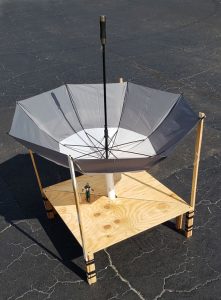


FederalizeVotingStandards.org advocates for eliminating the use of electronic voting machines
updated September 15, 2022

Audio: Alex Jones Speaks With Len Horowitz About Issues of the 2009 Swine Flu Outbreak
recorded April 29, 2009
running time 45 minutes


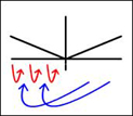
Deriving the Most Effective Activist Communication for Creating Political Change
updated February 18, 2020


_(14759015304).jpg)
.jpg)
.jpg)